Network topologies determine the flow of data through a network. This is
essential to know when designing or troubleshooting a network, irrespective of
what your role is. You need to understand the characteristics of the network
topology you are working with and identify how the topology affects network
performance and troubleshooting.
GLOSSARY:
-
The physical topology describes the placement of nodes and how they
are connected. For example, in one network, nodes might be directly
connected via a single cable; in another network, each node might connect
to a switch via separate cables. These two networks have different
physical topologies.
-
The logical topology describes the flow of data through the
network. For example, given the two cases of physical topologies, if in
both cases the nodes can send messages to one another, the logical
topology is the same. The different physical implementations (directly
connected via cable versus connected to the same switch) achieve the same
logical layout.
POINT-TO-POINT LINKS
-
A single link is established between two nodes. This is called a point-to-point connection. This can be physical or logical.
-
For example, on a WAN or MAN, two routers might be linked to each other
via intermediate networks and physical devices but still are a logical
point-to-point link, where each can address only the other router.
-
Either a physical or logical topology, it is the 1:1 relationship that
defines a point-to-point link.
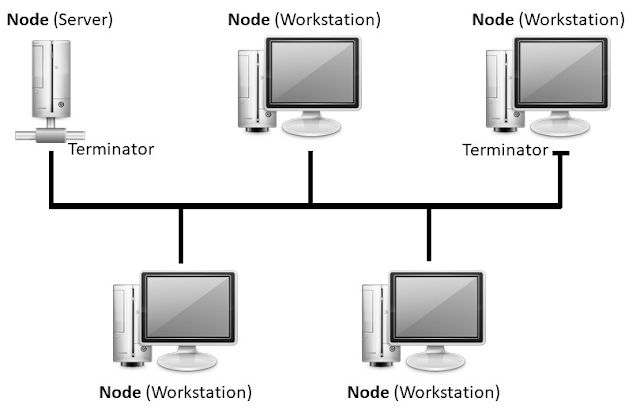
BUS TOPOLOGY
A physical bus topology with more than two nodes is a shared access
topology, meaning that all nodes share the bandwidth of the media. Only one
node can be active at one time. All nodes attach directly to a single cable
segment via cable taps. A signal travels down the bus in both directions from
the source and is received by all nodes connected to the segment. The bus is
terminated at both ends of the cable to absorb the signal when it has passed
all connected devices.
Bus Networks are comparatively difficult to reconfigure (adding or removing
nodes can disrupt the whole network), impose limitations on the maximum number
of nodes, and are difficult to troubleshoot a cable fault. Most importantly, a
fault anywhere in the cable means that all nodes are unable to
communicate.
|
|
Physical Bus Topology
|
A logical bus topology is one in which nodes receive the data
transmitted all at the same time, regardless of the physical wiring layout
of the network. Because the transmission medium is shared, only one node can
transmit at a time.
STAR TOPOLOGY
In a star topology network, each endpoint node is connected
to a central forwarding node, such as a hub, switch, or router. The
central node is usually a fast, self-contained computer and is responsible
for routing all traffic to other nodes. The star topology is the most widely
used physical topology. For example, a network that is based around a
single Internet router that can connect to a cable or wirelessly.
The star topology is easy to reconfigure and easy to troubleshoot because
all data goes through a central point, which can be sued to monitor and
manage the network. Faults are automatically isolated to the media, network
card, or the hub, switch, or router at the centre of the star.
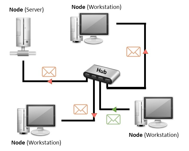
PHYSICAL STAR-LOGICAL BUS TOPOLOGY
A physical star network can be used to implement a
logical bus topology. When a device such as a hub is used
at the centre of the star, transmission is still repeated to each node.
Logically, the topology works like a single cable bus and the bandwidth is
still shared between all nodes. This means that some of the limitations of a
physical bus topology are retained.
|
|
Physical Star topology with logical bus topology implementation
|
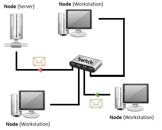
PHYSICAL STAR-LOGICAL STAR TOPOLOGY
When a device such as a switch is used at the centre of the star, the bus
element is reduced to the link between each node and its switch port. Taking
the network as a whole, both the physical and logical topology is a star.
The way the switch operates allows each node to use the full bandwidth of
the network media, and it allows nodes to communicate on the network
simultaneously. Faults are isolated to the link between a node and the
switch or to the switch itself.
|
|
Physical and logical star topology implementation
|
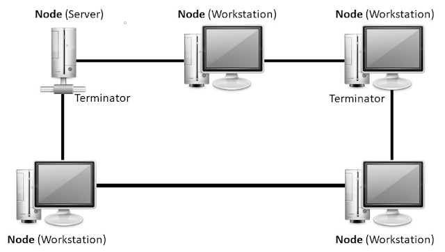
RING TOPOLOGY
In a physical ring topology, each node is wired to its neighbour in a
closed loop resulting in the creation of a circular data path. A nod
receives a transmission from its upstream neighbour and passes it to its
downstream neighbour until it reaches its destination.
The physical ring topology is no longer used on LANs, but it does remain a
feature of many WANs.
|
|
Implementation of Ring Topology
|
MESH TOPOLOGY
Mesh network topologies are commonly used in WANs, especially public
networks like the Internet. In theory, a mesh topology is a network setup
where each computer and network device is interconnected with one another.
The number of links required by a full mesh is expressed as n(n-1)/2,
where n is the number of nodes. For example, a network of just
five nodes would require ten links, while a network of 45 nodes would need
990 links! However, a hybrid approach is often used, with only the
most important devices interconnected in the mesh, perhaps with extra links
for fault tolerance and redundancy. Hence, it is referred to as a
partial mesh.
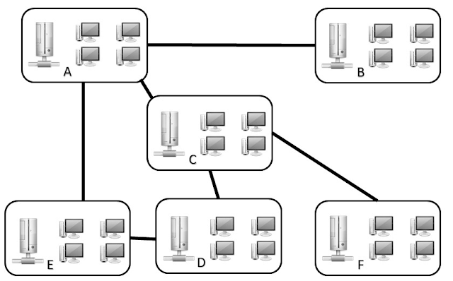
|
|
Partial Mesh Implementation
|
We hope this helps. If any suggestions or doubts you can add a comment and
we will reply as soon as possible.


%20Cover.jpg)

%20Cover.jpg)


No comments:
Post a Comment